Microfiltration and Ultrafiltration
As previously outlined, clarification combined with multimedia filtration has long been common technology for makeup pretreatment, with a primary goal of suspended solids removal upstream of high-purity makeup water systems. Additional membrane technologies, most notably micro- and ultrafiltration, have emerged as methods to further reduce suspended solids loading on RO membranes and ion exchange resins. Applications have been extended to municipal water and wastewater treatment, food and beverage production, and the oil and gas industry. Often, these systems serve as direct replacements for conventional suspended solids clarification and multimedia filtration.
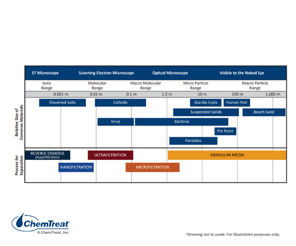
Figure 2.1 illustrates the filtration ranges of MF, UF, nanofiltration (NF), and RO. MF and UF are strictly for particulate filtration, while NF and RO remove dissolved ions.
There are three potential designs for MF/UF membranes:
- Hollow fiber
- Tubular
- Spiral wound
The hollow fiber design is most common, with pressurized and vacuum systems available. An example of a pressurized system is included below.
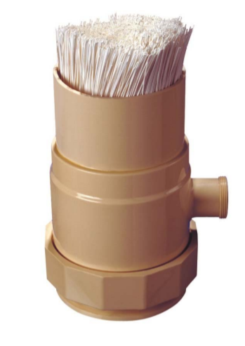
Figure 2.27. Cutaway view of the spaghetti-like hollow fiber membranes in an MF pressure vessel. Photo courtesy of the Pall Corporation.
An outside diameter of 0.7–1.5 mm and an inside diameter of 0.3–0.9 mm are the common dimensions for each membrane .
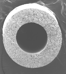
Figure 2.28. Magnified view of a single membrane from Figure 2.27. The flow path in these membranes is outside-in. Photo courtesy of the Pall Corporation.
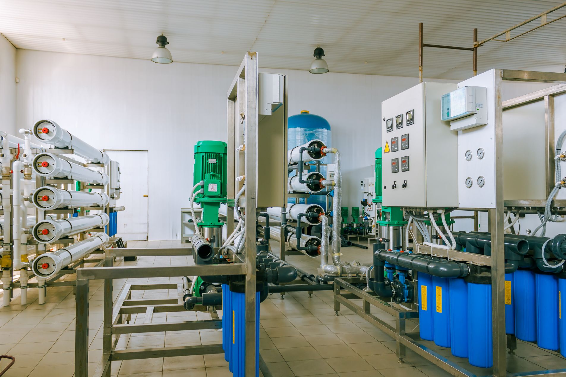
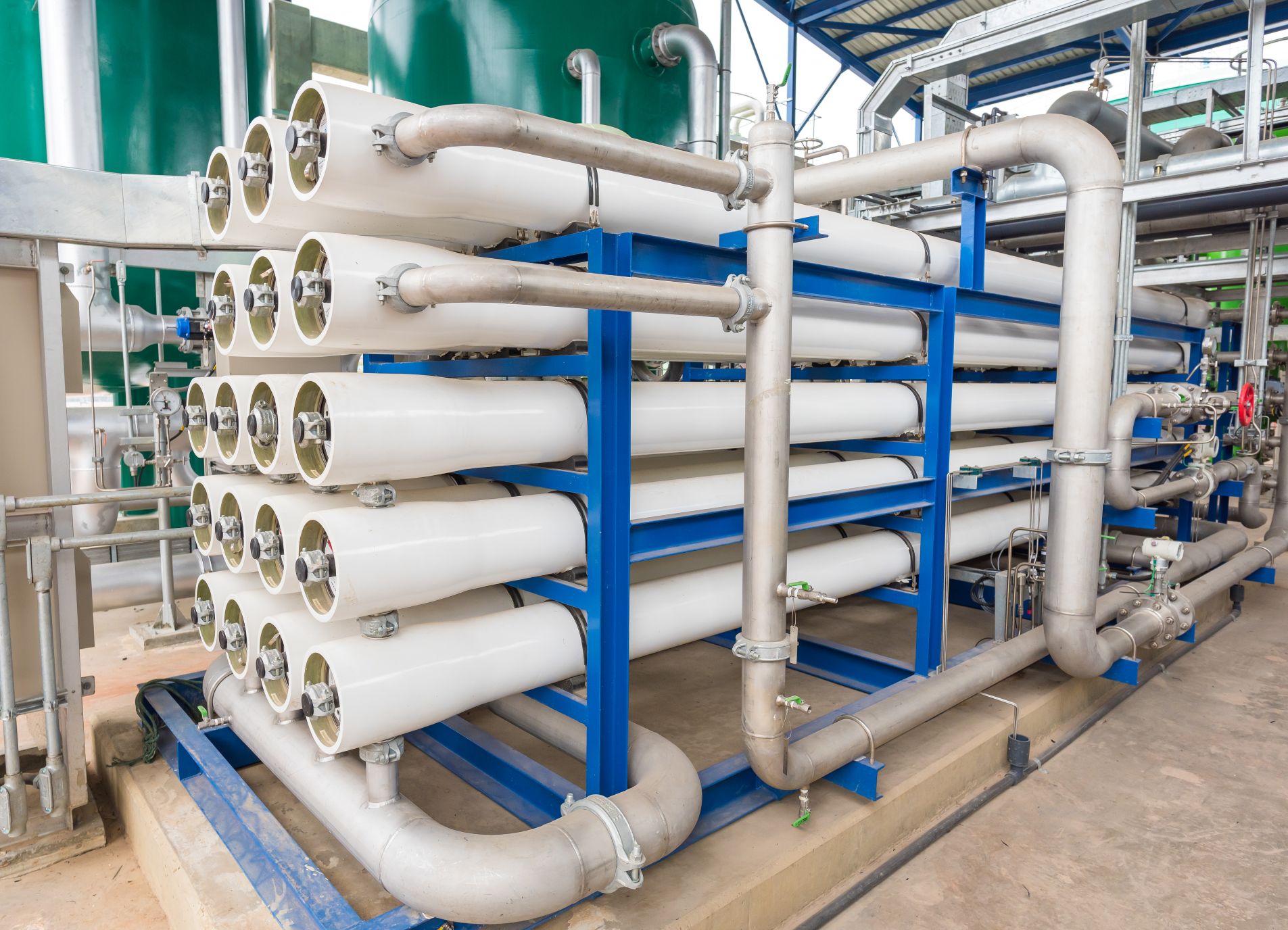
The figure below shows the pressure vessel arrangement for a 300-gpm microfiltration system.
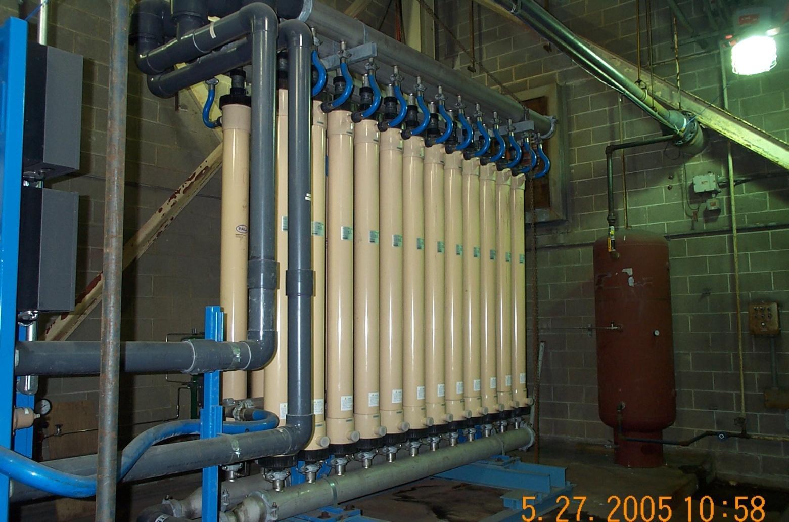
Figure 2.29. Pressure vessel configuration for a 300-gpm system.
Photo by Brad Buecker.
Polyethersulfone (PES), polyvinylidene fluoride (PVDF), polypropylene (PP), and polysulfone (PS) are each examples of typical membrane materials, with PES and PVDF being the most common. Each is hydrophilic, meaning the lumen surface becomes completely wetted, offering resistance to organic fouling. PES has slightly superior permeability than PVDF. Regarding off-line cleaning, PES has a higher caustic tolerance (for removal of organics and microbiological matter during off-line cleanings), while PVDF has a higher chlorine tolerance and membrane durability. These are important factors when deciding which material is better for a particular water source.
The multimedia filters outlined earlier in the chapter can produce effluent with turbidity approaching 1 NTU, while MF and UF effluent is typically much cleaner. For example, a microfilter installed as a direct replacement to an aging clarifier lowered the turbidity of feedwater to an RO unit from 1.0 NTU to less than 0.05 NTU1. This led to dramatically-reduced RO cartridge filter and membrane cleaning, and extended membrane life.
Pressurized systems have an inside-out or outside-in flow path. In contrast, submersible designs, where membranes are suspended in a tank with the feedwater, utilize an outside-in flow path, with a mild vacuum drawing the water into the membranes’ central core.
Common criteria of membrane or system selection include:
- Inside-out flow path is suitable for low concentrations of suspended solids.
- Outside-in is superior for higher levels of suspended solids because of the better backwashing efficiency.
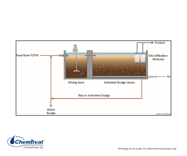
- Submersible membranes are common for high TSS applications, such as wastewater/reclaim water treatment in a membrane biological reactor (MBR). The membranes are placed at the effluent end of the vessel to maximize residence time for the microbiological reactions to take place.
Outside-in membranes have a surface area approximately three times that of inside-out modules, while submersible systems typically operate at a lower flux rate than pressurized systems.
Flux rate represents the volumetric flow rate divided by the membrane surface area, and it is a key measurement of MF/UF output and performance. Common flux rate measurements are gallons/ft2/day, or liters/m2/hr. The achievable or required flux rate for any application depends upon the membrane manufacturer, flow path, membrane material, water characteristics, and water temperature. Flux is influenced by the trans-membrane pressure (TMP), which is the difference between the feed and filtrate pressures.
Calculating flux and TMP as a ratio provides the permeability, expressed as gfd/psi, of the system, which can be used to determine operational performance.
J = Q/A
Where J = filtrate flux (gfd).
Q= filtrate flow in gallons per day (gpd).
A = membrane surface area (ft2).
TMP = ((PT + PB)/2) – PF
Where TMP = Transmembrane pressure (psi).
PT = Pressure of feedwater at the top of the filter (psi).
PB = Pressure of feedwater at the bottom of the filter (psi).
PF = Filtrate pressure (psi).
The term specific flux refers to filtrate flux that has been normalized for transmembrane pressure.
FTM = F/ TMP20°C
Where FTM = Specific flux (gfd/psi).
F = filtrate flux (gfd).
TMP20°C = Temperature-compensated transmembrane pressure (psi).
MF/UF utilizes a combination of crossflow and dead-end filtration where the feedwater flows parallel to the membrane surface, allowing particulates to accumulate within the membranes. The particles must be periodically removed with a backwash/air scour process. For example, in the system shown in Figure 2.29, the typical production sequence is 20 minutes followed by a one-minute backwash/air scour. While the backwash in this application is initiated on a timed basis, backwash triggered by a rise in TMP can also been considered as an alternative.
Some waters may contain impurities that cause fouling beyond the “normal” suspended solids which exist in surface waters or are present in the effluent of an upstream clarifier/softener system. For example, because of their small size, colloids may plug membranes. Fine iron particles can do the same. Organic coagulants or flocculants can adsorb on the membrane surface. Oil and grease are potential foulants as well, and they can quickly blind membranes and are difficult to remove. Microbiological fouling is also of concern. If the membranes are PES or PVDF material, however, oxidizing biocide feed upstream of the unit is common to minimize microbiological fouling.
An additional feature of MF/UF designs is chemically enhanced backwash (CEB). After a set number of standard backwashes, CEB is initiated. CEB introduces a chemical or chemicals to target troublesome foulants. For example, if iron oxides are a problem, citric acid is a common choice. Citric acid lowers pH but is a chelant that can solvate iron. If organic compounds and/or microbes are problematic, CEB will typically include caustic and bleach.
TMP trends and permeability studies are beneficial for establishing CEB frequency and chemical concentrations. Always consult and follow the manufacturer’s guidelines to evaluate the chemical tolerance of the membranes. A short, forward flush following a CEB is common to prevent residual chemicals from entering the produced water.
Despite the use of CEB, particulates will gradually accumulate, requiring a clean-in-place (CIP) procedure approximately once a quarter or at a similar interval. While CIP is an off-line procedure, it can typically be performed within a standard work shift. Many of the similar CEB chemicals, such as citric acid, caustic, bleach, are also used for CIP in higher concentrations. Examples include:
- Caustic cleanings, pH target values vary for different materials of construction: 10–11 for PVDF and 11.5–12.5 for PES.
- PVDF membranes generally have higher chlorine tolerance than PES.
- With citric acid cleaning for iron particulate fouling, a reducing agent like sodium bisulfite (SBS) can alleviate inner pore fouling. Dosages range from 1–3% citric acid with 0.2–0.4% SBS.
- Sometimes fouling may be so severe that a specialty chemical formula is required. These may be blends of surfactants, caustic, and chelants.
Best practice is to follow manufacturer’s guidelines when developing CIP procedures.
The key parameter in determining CIP frequency is an increase in TMP or a decrease in permeability. Figure 2.30 outlines a potential TMP performance curve over time. The temperature correction factor is applied to permeability data to account for seasonal variances and the determination of long-term membrane performance.
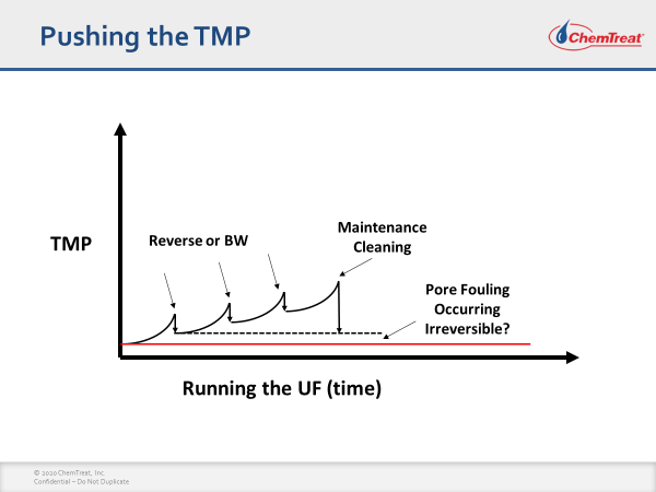
Figure 2.30. General outline of TMP increase and the effects of backwashing and
off-line cleaning.
With thousands of membranes in a typical hollow fiber unit, occasional membrane breaks are not uncommon. An increase in effluent turbidity may reveal a membrane failure. If suspected, the standard detection method is an offline pressure decay test or a vacuum hold test. These involve injecting air to the feed side of the membrane module and sealing the module. If the residual pressure is still within 90% of the initial pressure after five minutes, the test is successful. If not, an air bubble test is required to locate the broken membrane(s) and install a pin at the inlet end. It is important to note that some designs are more stable than others. For example, the unit shown in Figure 2.29 operated for years without a membrane failure.

 While applications such as cooling tower makeup or service water for washing plant infrastructure may be straightforward, other applications require high-purity water.
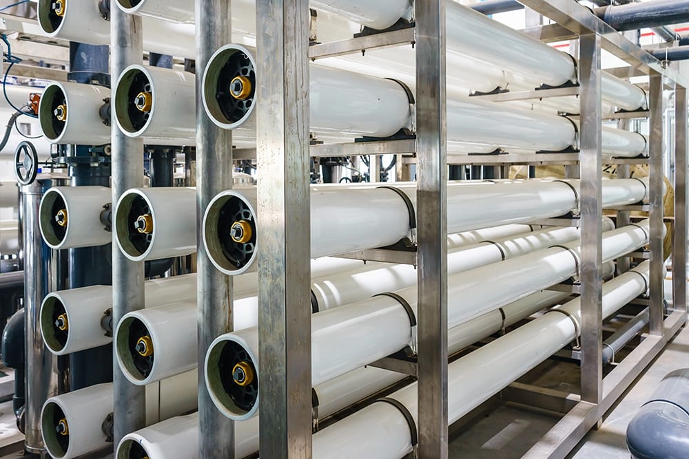
 ®-e1754665573754.png" alt="" width="600" height="384" srcset="https://staging.chemtreat.com/wp-content/uploads/2025/08/Figure-2.10.-Process-flow-diagram-of-Acti-Flo®-e1754665573754.png 600w, https://staging.chemtreat.com/wp-content/uploads/2025/08/Figure-2.10.-Process-flow-diagram-of-Acti-Flo®-e1754665573754-300x192.png 300w" sizes="(max-width: 600px) 100vw, 600px" />